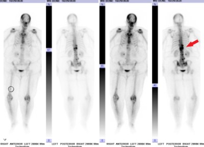
This is a 66 year old female who presents with severe back pain. She has known history of breast cancer with spread to multiple bones. Back pain started 8 weeks prior without specific traumatic event. No neurologic complaint.
  • All
  • Pre-Op
  • Intra-op
  • Post-op
Midsagittal MRI images of the thoracic spine obtained about 2 months prior to the procedure. T11 appears normal on the T2 image (left, arrow) but shows a small amount of hyperintensity (bright) on the STIR image (right).
Sagittal (left) and axial (right) images from lumbar MRI showing new T11 compression fracture (arrow)
Additional sagittal MRI images. T1 without (left) and T1 with contrast (right) images reveal abnormal enhancement, suggesting an underlying tumor in the bone of the T11 vertebral body.
Nuclear medicine bone scan showing abnormal radiotracer uptake in the lower thoracic spine (arrow) as well as other bone sites.
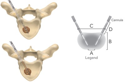
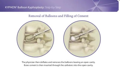
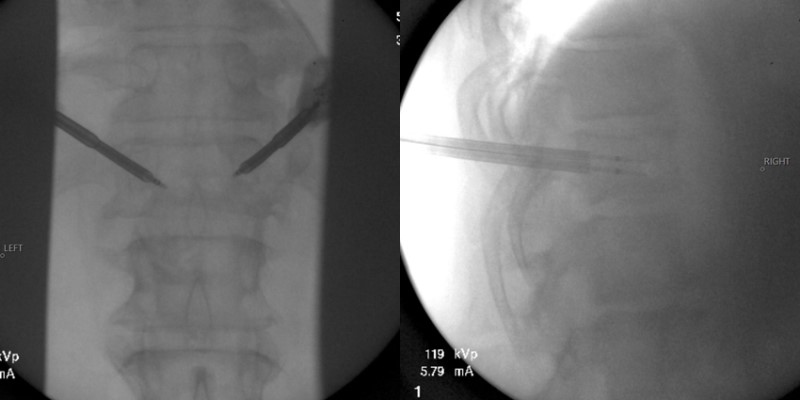
Diagrams demonstrating the transpedicular approach to the lesion. First, a drill is advanced into the vertebral body (top left), then a radio-frequency (RF) electrode is placed into the lesion (bottom left). When RF energy is applied an area around & between the electrodes is ablated (grey area on right image). [Courtesy of Medtronic OsteoCool]
Intraoperative fluoroscopic (x-ray) images showing the placement of the RF electrodes in the AP (left) and lateral (right) planes.
Diagrams demonstrating the transpedicular approach to the lesion for kyphoplasty. On the left, the kyphoplasty balloon is inflated within the vertebral body. On the right, it has been removed and bone cement is being injected into the cavity created. [Courtesy Medtronic Kyphon]
Intraoperative fluoroscopic (x-ray) images showing partially-inflated on the left and fully-inflated on the right kyphoplasty balloons in the Lateral plane.
Intraoperative fluoroscopic (x-ray) images showing fully-inflated kyphoplasty balloons in the AP plane.
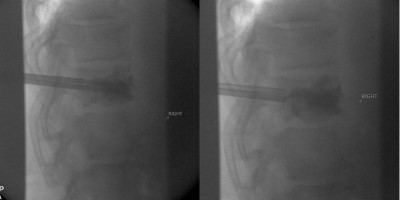
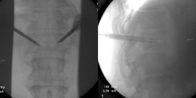
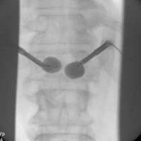
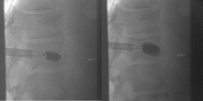
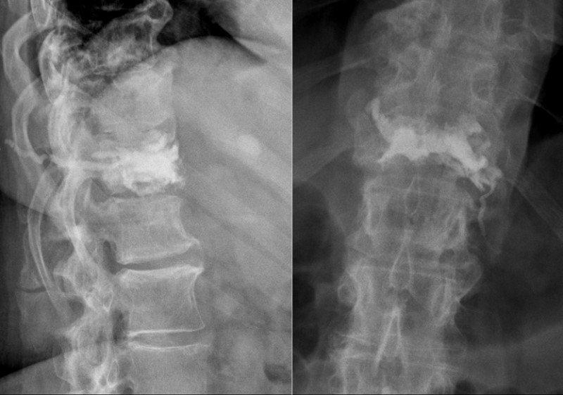
Intraoperative fluoroscopic (x-ray) images showing the injection of the kyphoplasty cement (methyl methacrylate) in the lateral plane. The left image shows a partial injection with the injection needles in place. The right image demonstrates the cement seen after full injection after the filling needles have been removed; access needles remain in place.
Intraoperative fluoroscopic (x-ray) images showing the injection of the kyphoplasty cement in the AP plane after complete injection and all needles have been removed.
Lateral (left) and AP (right) x-ray images taken 3 months postop showing the kyphoplasty cement filling the T11 body. Patient no longer has any pain.
Sagittal (left) and axial (right) CT images showing the cement in the T11 vertebral body. Taken from CT of the chest done for unrelated reasons.