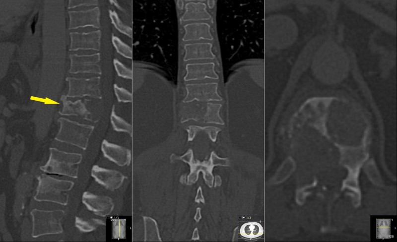
This is a 53 year old man presented with mid-lower back pain radiating to the left side of the lower chest and flank. He described the pain as severe after a minor fall 2 weeks prior but had mild back pain for about 4 months prior. He has no significant prior medical history.
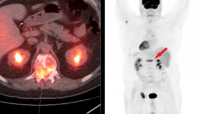
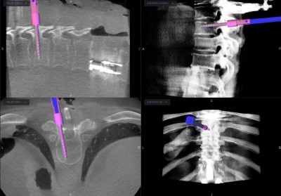
Images taken from a PET scan. On the left, the PET information is projected over a CT scan. The PET-active tumor is seen as an orange glow in the T12 vertebral body and in the spinal canal (the bright-orange spots to each side of the spine are the kidneys – a normal finding). On the right is a projection of the PET information in an A-P image from the brain (top) to the legs (bottom). PET-active areas are black. An abnormal spot is seen at T12 (arrow) as well as some other areas.
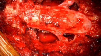
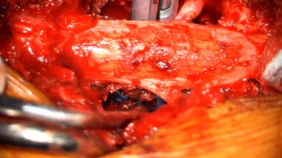
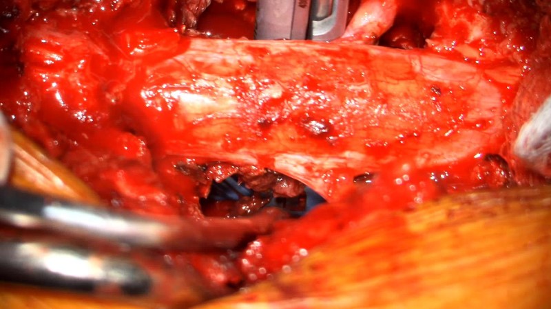
Intraoperative video showing the tumor resection cavity. The instrument moving is a suction tube used to remove blood and fluid from the operative field.
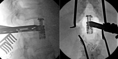
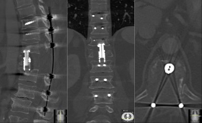
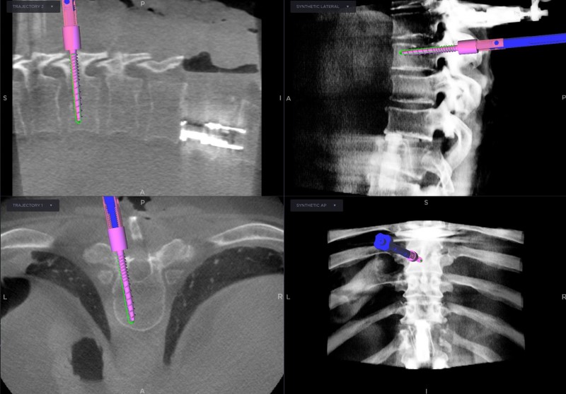
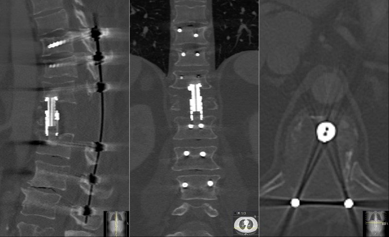
: Intraoperative fluoroscopic (x-ray) image showing the placement of the intervertebral cage into the T12 resection cavity in the lateral (left) and A-P (right) planes, spanning from T11 above to L1 below. The cage is attached to an insertion device. Once expended, the device will bear the weight of the patient.
- All
- Pre-Op
- Intra-op
- Post-op

